OVERVIEW
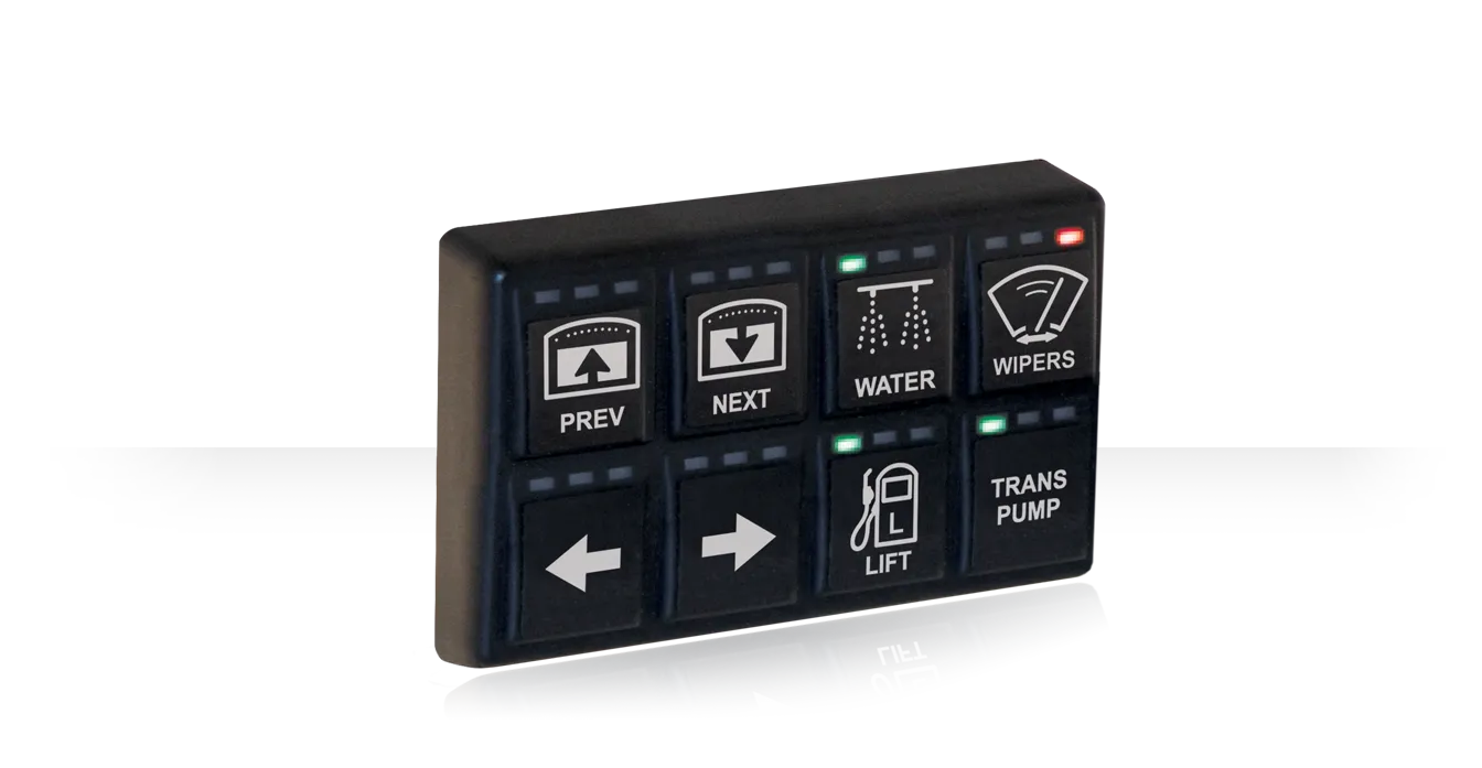
MoTeC’s multi-button backlit CAN Keypads provide a switching solution that can be customized and connected to any MoTeC PDM.
The buttons can be used as inputs to control the PDM and other devices in the vehicle. The three LED lights along the top of each button can be used to indicate the state of the devices.
Four separate Keypads, each with up to 15 keys, can be combined on a single CAN bus and controlled by the same PDM (factory configuration required).
41401 – 4 x 2 Button Keypad (includes labels x 4 sheets)
63044 – Replacement Labels x 4 sheets
- Small, lightweight and compact package
- Rugged design – vibration, and impact resistant for use in extreme environments
- Dust and water resistant – sealed to IP67
- Dimmable LED indicators above each button for real-time feedback
- Backlit buttons
- Pre-designed semi-transparent labels supplied
- Supports multiple key press combinations
- Simplified wiring – only 4 wires required for multiple buttons
- Short circuit and reverse polarity protection
Configuration
- All configuration is done via PDM Manager software:
- CAN addressing, function, backlight brightness, status LEDs etc.
Communications
- Single CAN bus
Capacity on CAN Bus
- Up to 4 Keypads, with up to fifteen keys each
Advise your dealer if multiple Keypads are required on the same CAN bus. Use of multiple Keypads will require the units to be pre-configured before supply.
LED Status Lights
- Colors: green, orange, red
Power
- Operating voltage: 8 to 32 V DC
- Operating current: 0.2 A maximum
- Reverse battery protection
- Short circuit protection
Ambient Operating Temperature
- -40 °C to 85 °C
Physical
- 1 x 4 pin Deutsch DT connector
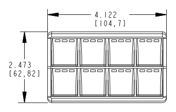
- Size (without connector): 104.7 x 62.82 x 15.52 mm
- Weight: 105 g
Mating Connector: MoTeC #68064
| Pin | Function | Pin | Function |
|---|---|---|---|
| 1 | Power | 3 | CAN-Hi |
| 2 | Ground | 4 | CAN-Lo |
The Keypad has a male 4 pin Deutsch DT connector molded into the back of it. The corresponding female connector should be wired as follows.
Power Wiring
The Keypad will continuously send CAN messages to the PDM, which will prevent the PDM from entering standby mode. There are two methods for wiring the supply to the Keypad.
- For vehicles with a battery isolation switch, configure the PDM to always power the Keypad. This will allow the Keypad buttons to be used for master start up functions, but the PDM will never enter standby mode. To minimize battery drain when the vehicle is not being used for extended periods, the battery isolation switch needs to be turned off.
- Wire a master switch or ignition key into a PDM input and configure the PDM to turn off all the outputs (including the Keypad) when the switch or key are turned off. This will allow the PDM to enter standby mode, minimizing battery drain.
PDM Global Setup
Keypad Setup
Keypad buttons can be allocated to control an input channel in a similar fashion to controlling the input pins of the PDM. Each input can then be used for multiple functions as required. See the sample configurations built into PDM Manager.
The three LED lights along the top of each button can be configured to indicate the state of devices. One example is: LED 1 (green) may be turned ON when the button output channel is active; LED 2 (orange) could be used to show that the output has gone into fault; LED 3 (red) could turn on if the output channel has faulted and stopped retrying.
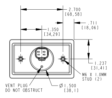
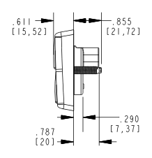
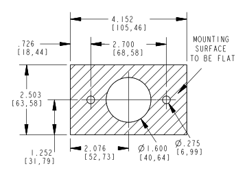
Dimensions are in inches and millimeters (in brackets).
4 x 2 Button Keypad
| Front | Back | |
|---|---|---|
| Side | Mounting surface |
|---|---|


Reviews
There are no reviews yet.